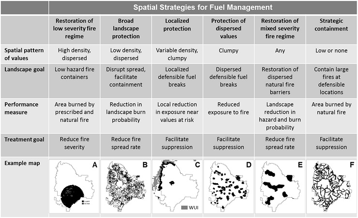

The choice of the most appropriate landscape fuel management strategy is determined by specific combinations of: (1) spatial patterns of human and ecological value, (2) fire management goals, (3) fire ecology, and (4) wildfire exposure as measured by likelihood and intensity. Collectively, these factors determine the extent to which long-term risk management emphasizes restoring natural fire regimes versus protecting highly valued resources and assets with suppression, and the most appropriate spatial fuel management strategy. Developing robust fuel management strategies where steep gradients exist for the above factors (e.g., wilderness adjacent to an urban interface) will be a challenge. Landscape fuel management tools (such as the Landscape Treatment Designer) can facilitate the development of these strategies.

Spatial framework for landscape fuel management. Strategies are determined by fire regime, fire management objectives, and the spatial pattern of values at risk. Black shaded areas in the maps depict fuel treatment areas within the example landscape. (A) Low hazard fire containers for dry forest restoration, (B) protection of dispersed values using the approach of Finney (2007) where treatments are arranged to maximize the reduction in spread rate, (C) defensible fuel breaks around a wildland urban interface (WUI), (D) defensible fuel breaks around dispersed values (e.g., critical wildlife habitat), (E) restoration of natural fire barriers (e.g., hardwood forest in a conifer matrix), and (F) high hazard fire containers surrounded by networks of defensible fuel breaks. Figure 10 from Ager et al. 2013.
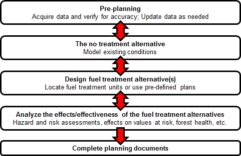
This section contains a fuel treatment planning scenario to highlight the use of ArcFuels10. The scenario is meant to serve as an example analysis used for planning documents (such as fire and fuels specialist reports for an environmental impact statement (EIS) or environmental assessment (EA)). Below is a simplistic flow chart of the fuel treatment planning process. ArcFuels10 was primarily designed to assist with the first four steps: pre-planning (only data update), the no-treatment alternative, designing and implementing fuel treatment alternative(s), and analyzing the effects/effectiveness of the fuel treatment alternatives. The last step, completing planning documents is not included because this is very specific to the project and location.

Simplistic flow chart of fuel management planning process. ArcFuels was designed to assist the middle processes: designing the no treatment alternative, designing fuel treatment alternative(s), and analyzing the effects of the fuel treatment alternatives.
Example exercises are provided for each of the first four steps in the planning process. The exercises in the following sections will use the demonstration data. If you are not already set up with the demonstration data see Demonstration Data to get everything loaded and linked.
The example exercises provided highlight the uses of ArcFuels in conjunction with other programs such as FVS/FFE-FVS, FlamMap5, ArcGIS, Excel, and Access to complete these processes. The example exercises are not all-inclusive but should provide a good example for fuel treatment planning.
Before starting with the Fuel Treatment Planning Scenario exercises, start with a clean map. You will not need any of the ArcMap layers created in the The ArcFuels10 toolbar section.
To begin with the Pre-Planning step go to: Pre-planning.